บทนำ
A PV monitoring system does more than record solar irradiance. Its measurement data is used to assess plant performance, identify potential losses, and support performance evaluation. In practice, the challenge is not simply choosing accurate sensors. The monitoring class, required parameters, sensor installation, calibration, and data quality all affect whether the collected data is representative and useful.
IEC 61724 is not simply a sensor specification. IEC 61724-1:2021 provides a framework for photovoltaic system performance monitoring, covering monitoring equipment, measurement methods, data quality, and monitoring classes. The required measurement setup can vary with the PV configuration and monitoring purpose. Bifacial systems, for example, may require additional irradiance measurements to account for rear-side contribution.
This guide explains the main IEC 61724 requirements and connects them with practical sensor selection. It covers monitoring classes, irradiance and temperature measurements, wind and soiling monitoring, sensor installation, calibration, data acquisition, and key points to check when specifying a PV monitoring system.
What Does IEC 61724 Mean for a PV Monitoring System?
IEC 61724-1:2021 provides requirements and recommendations for monitoring photovoltaic system performance. It covers the equipment, measurement methods, monitored parameters, and data quality needed to collect meaningful performance data from a PV system. In practical projects, it provides a common framework for deciding what should be measured and how the monitoring system should be configured.
It is not only about sensors. The value of PV monitoring data depends on the complete measurement process: Sensor → Installation → Data Acquisition → Data Quality → Performance Analysis. An accurate irradiance sensor, for example, cannot provide representative data if it is incorrectly positioned, poorly maintained, or connected to a system that records the measurements improperly. The same principle applies to temperature, wind, and soiling measurements.
For equipment selection, the monitoring class and required measurement parameters should be defined before selecting individual sensors. This provides a practical basis for matching sensor accuracy, measurement range, installation method, communication interface, and maintenance requirements to the actual PV project.
IEC 61724-1:2021: What Changed?
For anyone specifying a PV monitoring system, the 2021 edition matters because some of its changes affect how monitoring classes, irradiance measurements, and soiling measurements are configured. You do not need to read every clause to understand the practical impact. Three areas are particularly relevant when selecting and applying PV monitoring sensors.
Class C Was Removed
IEC 61724-1:2021 uses Class A and Class B monitoring systems, while the Class C category from the previous edition was removed. The monitoring class therefore needs to be established before defining the measurement equipment and sensor requirements for a project.
Bifacial PV Monitoring
Bifacial modules receive radiation on both the front and rear surfaces. For these systems, the monitoring configuration may need to consider rear-side irradiance and reflected radiation, depending on the PV design and monitoring purpose. This makes sensor type, measurement position, and installation geometry more important than simply choosing a sensor based on its accuracy specification.
Irradiance and Soiling Measurements
The 2021 edition also updated requirements related to irradiance measurement and soiling assessment. In practical projects, these measurements depend not only on the sensor itself, but also on calibration, installation, cleaning, and long-term measurement stability. For this reason, irradiance and soiling sensors should be considered as part of the complete monitoring setup rather than as standalone instruments.
The practical takeaway is simple: define the monitoring class and required measurements first, then select the sensors and installation method that match them. This becomes especially important when the plant uses bifacial modules or requires more detailed performance analysis.
IEC 61724 Class A vs. Class B
Class A provides more demanding monitoring requirements than Class B. The difference is mainly reflected in the required measurement quality, monitoring equipment, installation control, and maintenance of the PV monitoring system.
| Monitoring level | Higher measurement quality | Moderate measurement quality |
| Equipment requirements | More demanding | Less demanding |
| การติดตั้ง | Tighter control of measurement conditions | Simpler requirements |
| การบำรุงรักษา | More demanding | Less demanding |
| วัตถุประสงค์หลัก | Detailed performance monitoring | General performance monitoring |
Plant capacity alone does not determine the monitoring class. The project purpose, required measurement quality, PV configuration, and performance assessment requirements should be considered together. A larger plant does not automatically require Class A, just as a smaller plant is not automatically limited to Class B.
IEC Monitoring Class vs. Pyranometer Class
One point is easy to miss when buying a pyranometer: IEC 61724 Class A/B and ISO 9060 Class A/B are not the same classification.
IEC 61724 Class A and Class B describe the PV performance monitoring system, while ISO 9060 Class A and Class B describe the performance classification of pyranometers. The two classifications are related to measurement quality, but they apply to different things.
This distinction matters when specifying irradiance sensors. First define the monitoring requirements of the PV project. Then select a pyranometer according to the required measurement performance, applicable ISO classification, measurement plane, calibration, and installation conditions.
If you are comparing Class A and Class B pyranometers, our guide “ไพราโนมิเตอร์คลาส A กับคลาส B: คุณต้องการแบบไหน?” explains the difference between the two ISO 9060 classifications and the practical points to check before purchasing.
What Sensors Are Used in IEC 61724 PV Monitoring?
PV monitoring systems use different sensors to measure irradiance, module temperature, weather conditions, and soiling. The required setup varies with the monitoring class and PV plant design. Sensor selection should start with the parameters needed for performance analysis.
POA Irradiance Sensor
POA irradiance measures solar radiation received on the same plane as the PV modules. It provides a reference for the solar energy available to the array and is an important input for performance analysis.
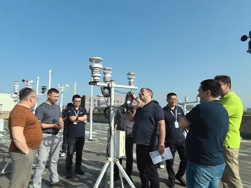
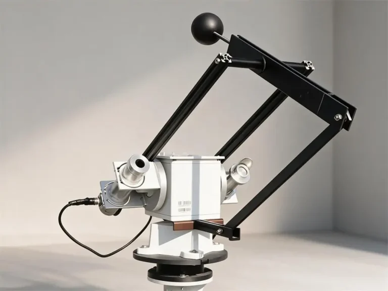
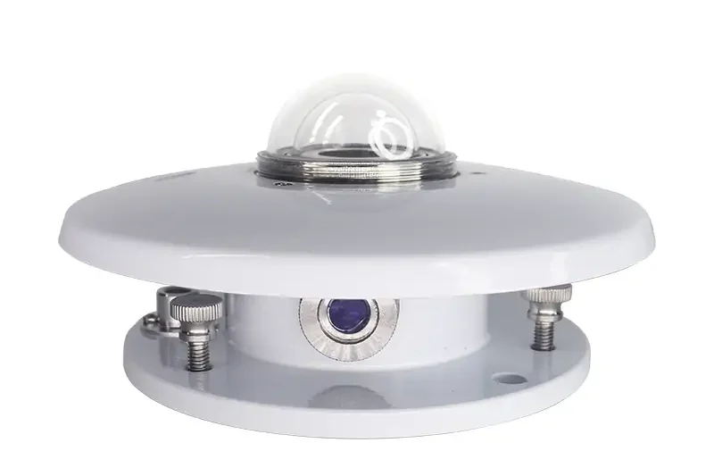
Sensor tilt and orientation should match the PV array. Shading and obstructions should also be avoided. Yantai Sensor TBQ-2C is a thermopile pyranometer designed for solar radiation measurement and can be used in PV irradiance monitoring.
GHI Measurement
GHI measures solar radiation received on a horizontal surface. It provides a reference for the solar resource at the site and can support PV performance analysis.
GHI and POA should not be treated as interchangeable measurements. GHI uses a horizontal reference plane, while POA follows the orientation of the PV array. TBQ-2C can be used for global solar radiation measurement.
โมดูลเซ็นเซอร์วัดอุณหภูมิ
Module temperature affects PV electrical output and can differ considerably from ambient air temperature. Measuring the module directly gives more useful information when interpreting changes in power output.
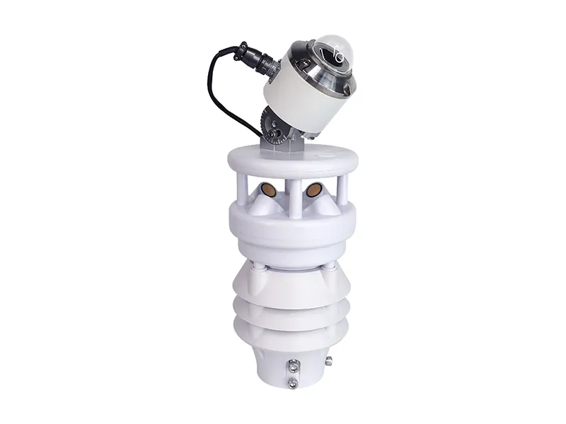
The sensor should maintain good thermal contact with a representative module. Yantai Sensor’s module temperature sensor supports PV environmental monitoring, while XF500S-CWB integrates module temperature measurement into a compact PV monitoring system.
Ambient Temperature and Weather Sensors
Ambient temperature provides basic environmental information for PV performance analysis. Wind speed and direction help explain heat dissipation from the modules and changing site conditions.
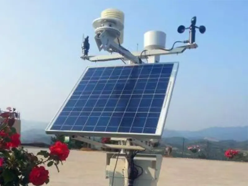
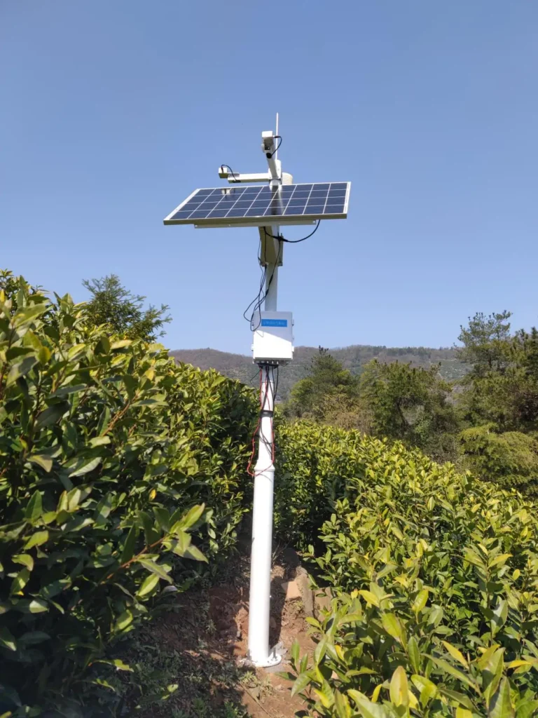
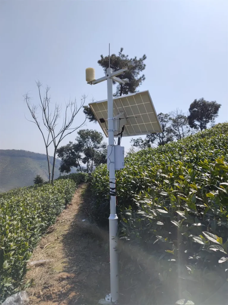
XF500S-CWB integrates ambient temperature, humidity, module temperature, wind speed, wind direction, atmospheric pressure, and POA radiation in one compact monitoring unit. It is suitable for projects that need several PV environmental parameters from a single device.
Soiling Sensor
Dust and other surface contamination can reduce the radiation reaching PV modules. A soiling sensor helps quantify this effect and provides useful data for cleaning decisions.
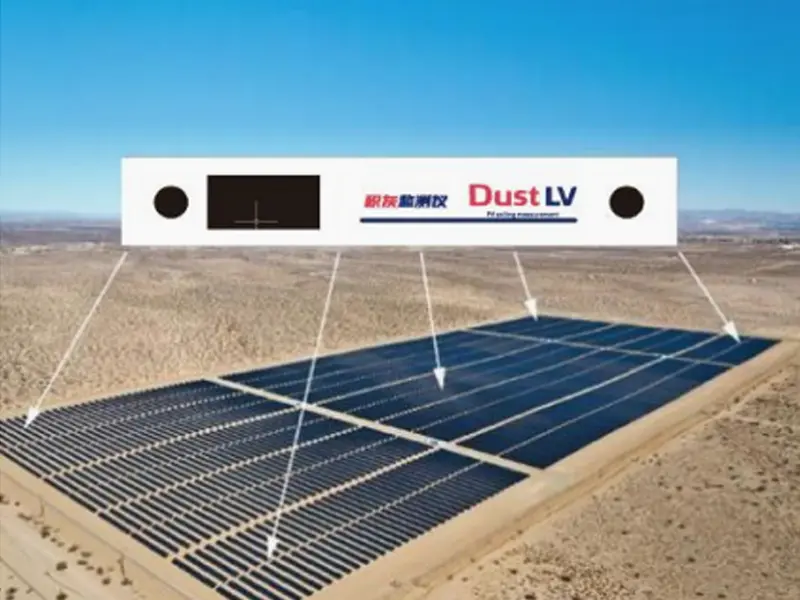
DustLV is designed for photovoltaic module pollution monitoring. It tracks surface contamination through optical measurement and provides a pollution status index for ongoing monitoring.
Rear-Side Irradiance and Albedo for Bifacial PV
Bifacial modules also receive radiation on their rear surface. Monitoring may therefore include rear-side irradiance or reflected radiation, depending on the PV layout and evaluation purpose.
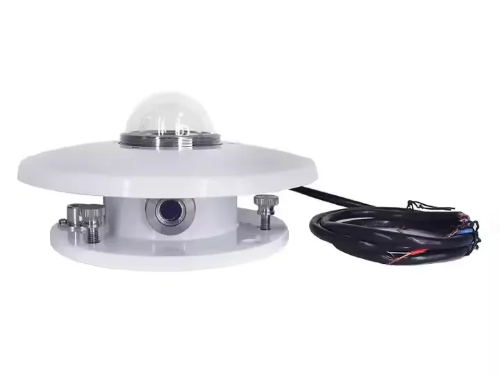
Sensor position becomes particularly important in this application because rear-side radiation varies with module height, row spacing, ground surface, and surrounding conditions. RYQ-3 can be configured for PV radiation monitoring applications that require additional radiation measurements.
How to Match PV Parameters with Sensors?
Sensor selection should start with the parameter that needs to be measured, then consider the PV plant design, monitoring purpose, measurement quality, and installation conditions. The table below gives a practical reference for matching common PV monitoring parameters with suitable sensor types.
| PV Parameter | What It Tells You | Typical Sensor |
| POA irradiance | Solar radiation received by the PV array plane | Pyranometer / irradiance sensor |
| จีเอชไอ | Solar radiation on a horizontal plane | ไพราโนมิเตอร์ |
| Module temperature | Operating temperature of PV modules | Module temperature sensor |
| อุณหภูมิแวดล้อม | Surrounding air temperature | Temperature sensor |
| ความชื้น | Site moisture and environmental conditions | Humidity sensor |
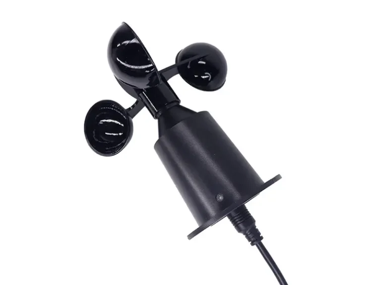
| ความเร็วลม | Air movement and module cooling conditions | เครื่องวัดความเร็วลม |
| ทิศทางลม | Local airflow conditions | เซ็นเซอร์วัดทิศทางลม |
| สิ่งสกปรก | Module surface contamination and related losses | Soiling sensor |
| Rear-side irradiance | Radiation available to bifacial module rear surfaces | Irradiance sensor |
| Albedo | Radiation reflected by the ground surface | Albedo measurement system |
How Many Sensors Does a PV Plant Need?
There is no fixed sensor quantity for every PV plant. The required number depends on the monitoring class, plant size, site layout, module orientation, tracker configuration, bifacial design, and local environmental variation.
A practical approach is to place enough sensors to capture meaningful differences across the PV field. The goal is not to install as many sensors as possible, but to obtain representative measurements for the areas being monitored.
For procurement, sensor quantity should therefore be defined together with the plant layout and monitoring requirements rather than selected from plant capacity alone.
Where Should PV Monitoring Sensors Be Installed?
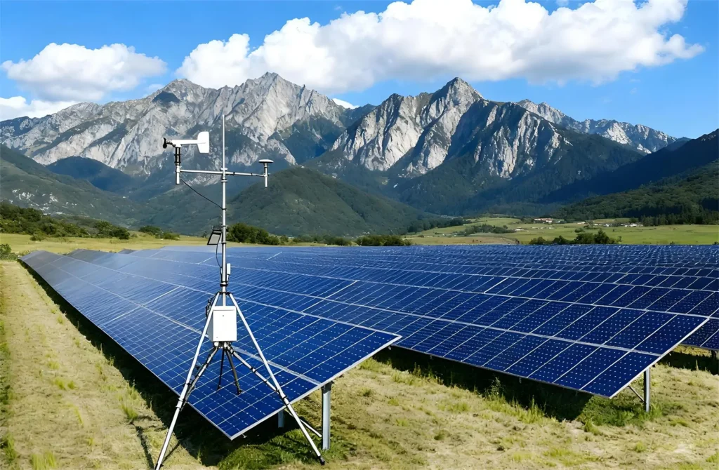
Sensor placement directly affects whether the collected data represents the PV field. Each sensor should therefore be installed according to what it measures and the conditions around the array.
Irradiance Sensor
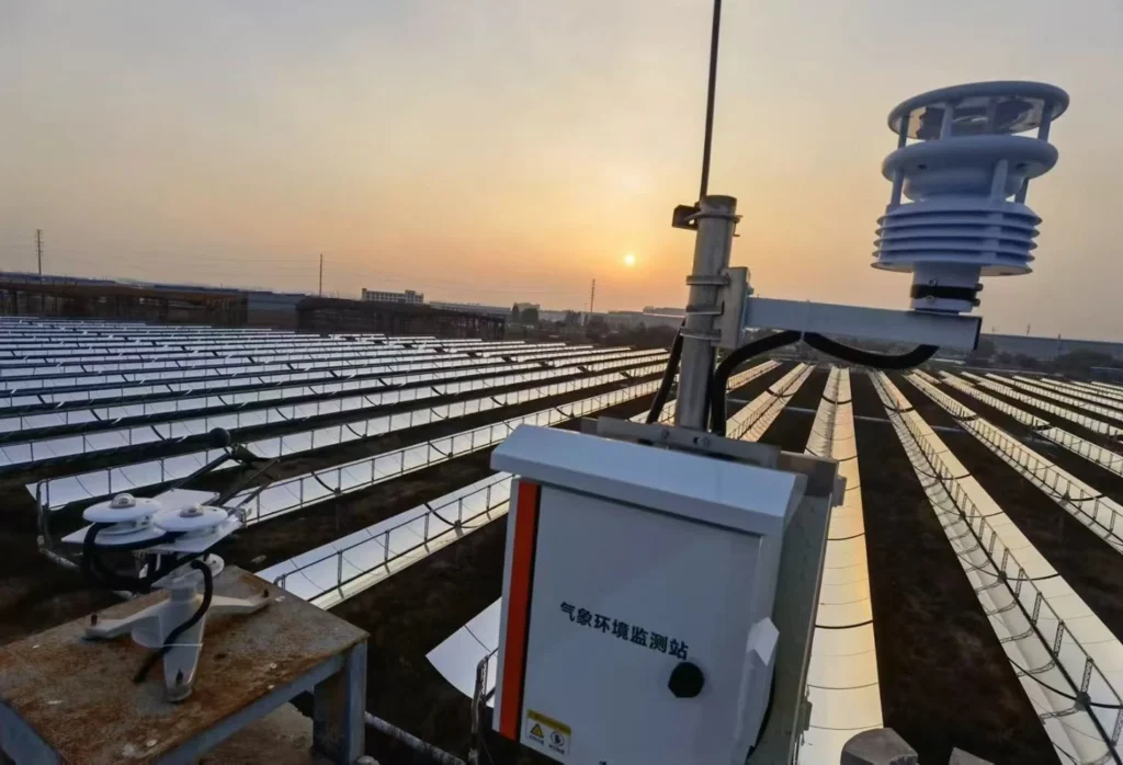
Install the irradiance sensor in the same plane and orientation as the PV array being monitored. Avoid shading from modules, structures, trees, or other equipment, and keep the sensor accessible for cleaning and inspection.
โมดูลเซ็นเซอร์วัดอุณหภูมิ
Mount the sensor firmly on a representative PV module and maintain stable thermal contact with the module surface. The selected module should reflect typical operating conditions in the monitored area rather than an unusual location within the array.
เซ็นเซอร์ลม
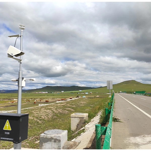
Choose a position with unobstructed airflow and keep the sensor away from structures, equipment, or other sources of local turbulence. The installation height should suit the PV layout and the purpose of the measurement.
Soiling Sensor
Place the soiling sensor where dust exposure is representative of the PV modules being monitored. It should be easy to access for cleaning, inspection, and periodic maintenance.
Sensor Accuracy, Calibration and Maintenance
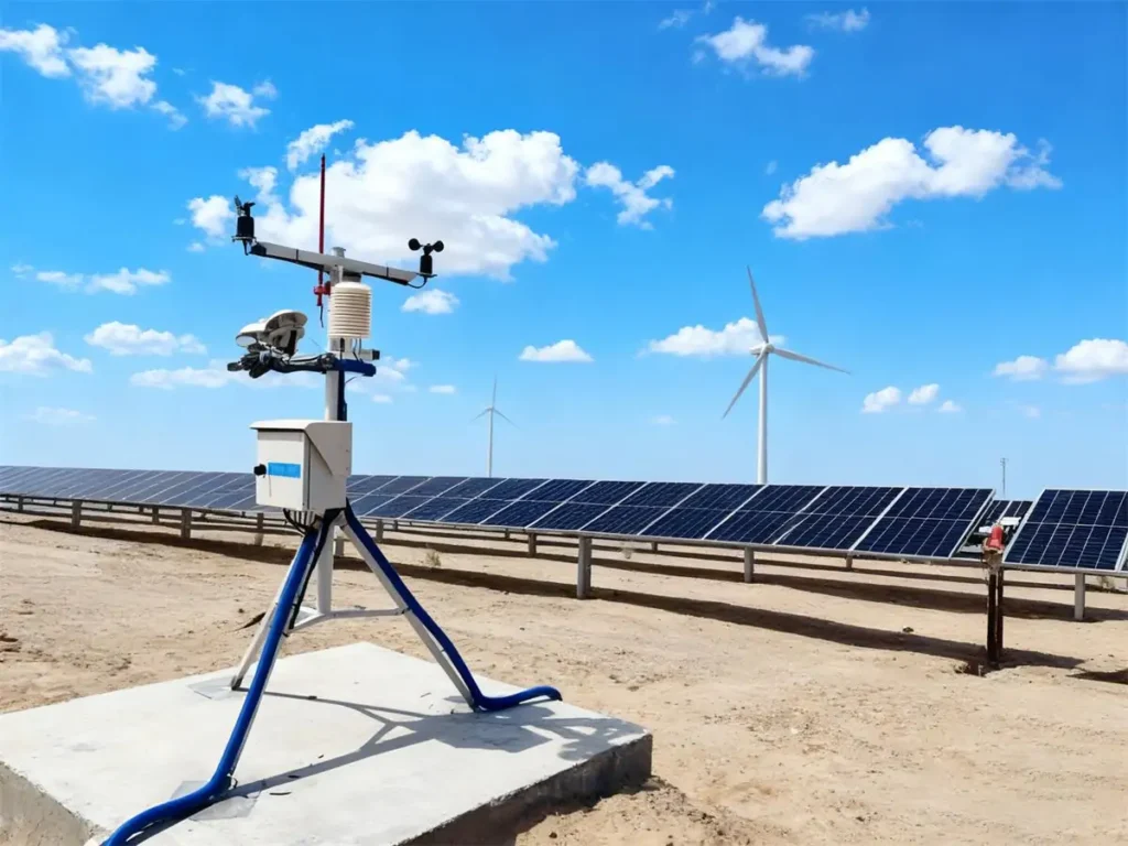
A sensor may look good on paper and still give poor data in the field. When comparing PV monitoring sensors, check the measurement range, response, stability, operating conditions, and the measurement requirements that apply to the project. The sensor specification needs to make sense for the conditions where it will actually be installed.
Check Accuracy
Accuracy is only one number on a datasheet. Look at the measurement range, response time, stability, and operating temperature as well. For irradiance sensors, the measurement performance and installation conditions are especially important because small errors can affect later performance analysis.
Check Calibration
Ask for the calibration certificate before placing the order. It is also worth checking the calibration date, traceability, and recommended recalibration interval. These details become important when the monitoring data will be used for long-term plant assessment or compared with other measurement records.
Check Maintenance
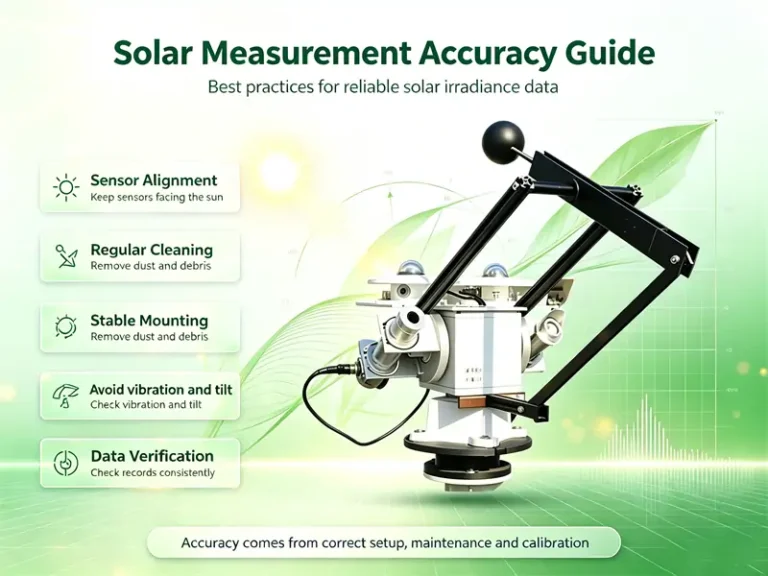
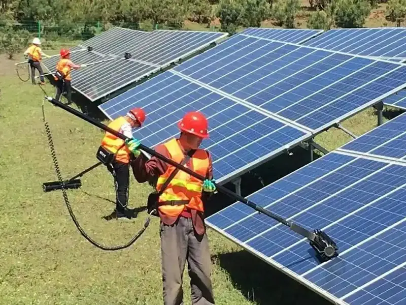
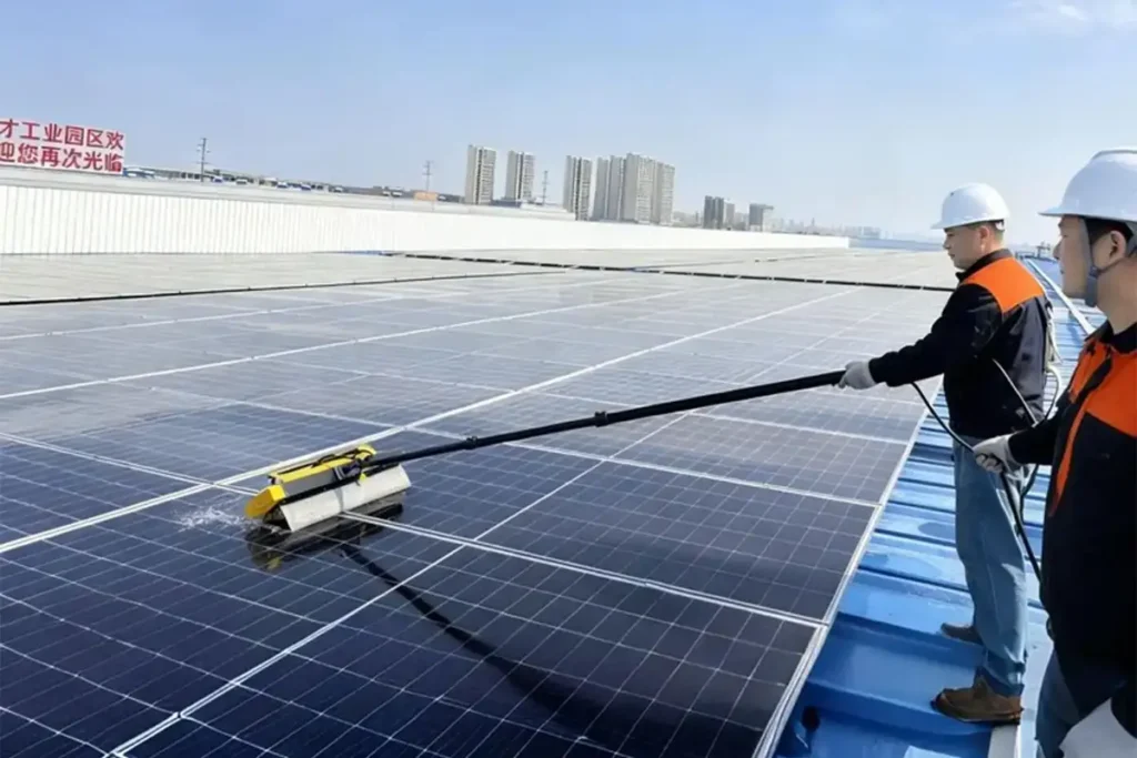
Most maintenance is straightforward: keep the sensing surface clean, check the sensor position, inspect cables and connectors, and make sure the mounting has not shifted. The required frequency depends on the site. Dusty locations may need more frequent cleaning, while exposed outdoor equipment needs regular checks for weather or mechanical damage.
Sensor accuracy is only one part of measurement quality. Installation, calibration, and maintenance also affect the final data.


How IEC 61724 Data Supports PV Performance Analysis?
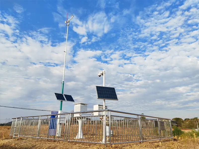
Once the monitoring system is running, each sensor provides a different piece of the performance picture. Irradiance shows how much solar energy was available to the PV array, while module temperature helps explain temperature-related changes in output. Wind and other environmental measurements add context to changing site conditions, and soiling data can help identify losses caused by dust and surface contamination.
These measurements become much more useful when they are analyzed together with the plant’s electrical output. IEC 61724 provides a common framework for collecting and using this data, making it easier to track performance, investigate unusual output, and understand the factors behind changes in generation. This is why sensor selection matters. The quality and representativeness of the measurements directly affect the quality of the performance analysis.
สรุป
IEC 61724 provides a practical framework for collecting and using PV performance data. For a monitoring project, the key is to match the monitoring class and PV configuration with the right measurement parameters, sensor specifications, installation conditions, and maintenance plan. Good monitoring depends on the whole measurement setup, not a sensor specification alone.
Yantai Sensor provides irradiance, temperature, weather, and soiling sensing options for PV monitoring applications, with different measurement ranges and communication interfaces available for project requirements. ติดต่อ Yantai Sensor and share your PV plant configuration and monitoring parameters with our team. We can help you discuss a suitable sensor setup for your project.