Introduction
PV monitoring installation involves more than mounting sensors and connecting cables. Measurement points need to reflect the site and monitoring objectives, while irradiance sensors must be aligned with the intended measurement plane. Sensor output signals and data logger inputs also need to be compatible. If these details are overlooked, the PV monitoring system may collect data that is incomplete, inconsistent, or unsuitable for performance analysis.
This guide explains the main steps in PV monitoring installation, including site assessment, sensor placement, wiring, communication setup, data checks, and routine maintenance. It is intended for EPC contractors, system integrators, project engineers, and O&M teams planning or commissioning PV monitoring systems. It also clarifies the difference between environmental monitoring and electrical performance monitoring, since the two involve different measurements and installation requirements.
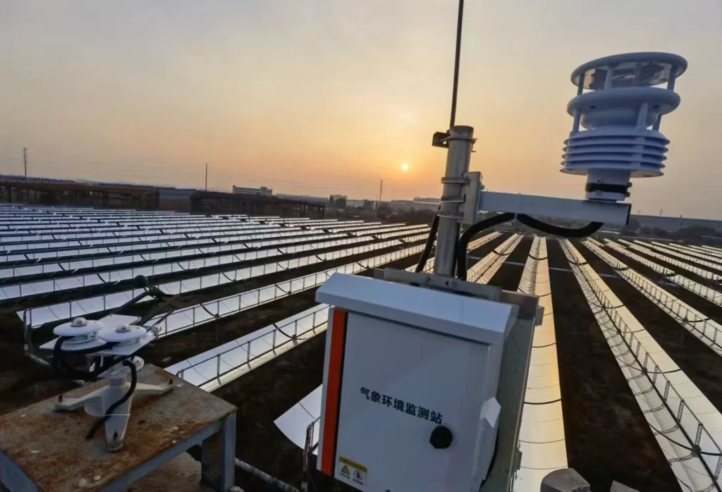
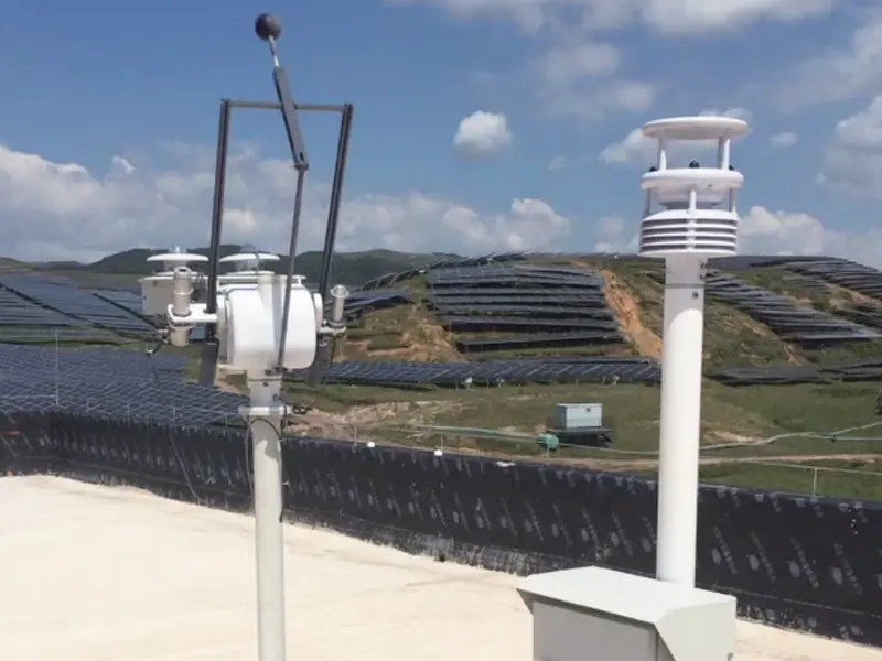
What Does a PV Monitoring System Need to Measure?
A solar monitoring system installation combines environmental measurements with operating data from the solar plant. Which parameters are needed depends on the project scope. Before installation, engineers need to identify which conditions will be measured, which equipment will supply the operating data, and how the two datasets will be used.
Electrical Performance and Environmental Monitoring
Electrical monitoring tracks how the PV equipment operates, including inverter output, energy yield, alarms, and, where the PV monitoring system supports it, string-level voltage and current. Environmental monitoring measures site conditions that help explain changes in PV performance, typically including solar irradiance, module temperature, ambient temperature, and wind speed and direction.
The two data sets complement each other but serve different purposes. For example, irradiance measurements provide context for changes in power output, while module temperature helps engineers assess the effect of operating temperature. Their installation and verification requirements also differ. An environmental monitoring system does not automatically include inverter commissioning, grid protection, or other electrical control functions; these should be defined separately in the project scope.
Main Components of a PV Environmental Monitoring System
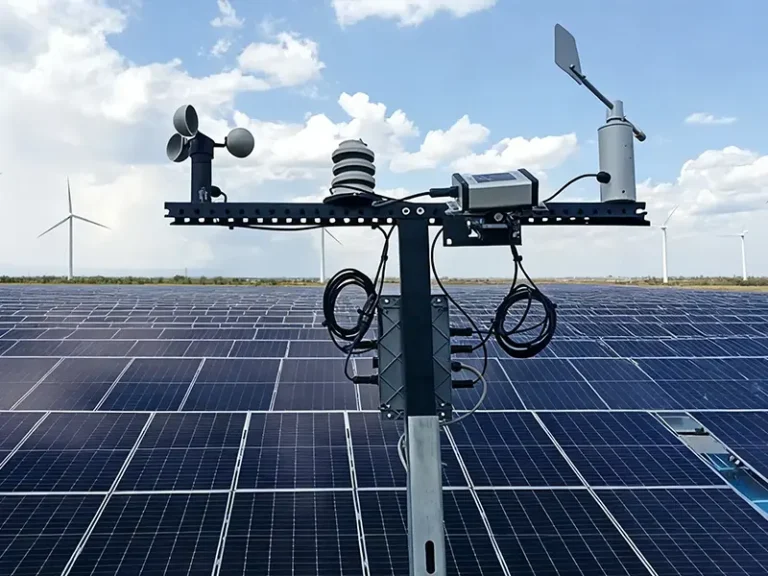
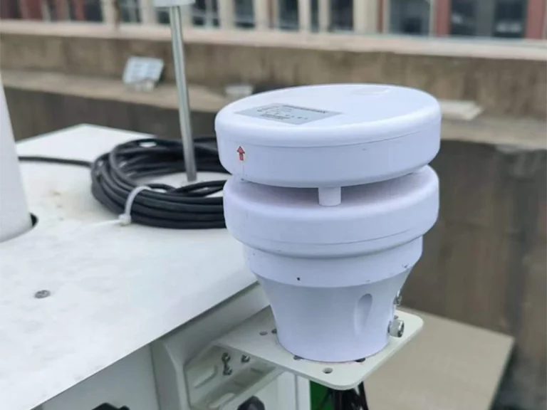
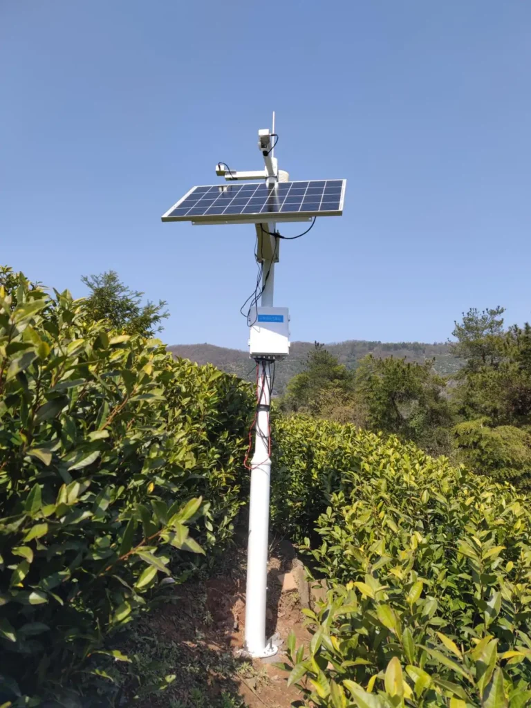
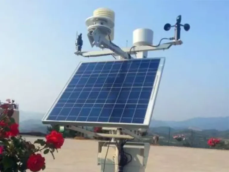
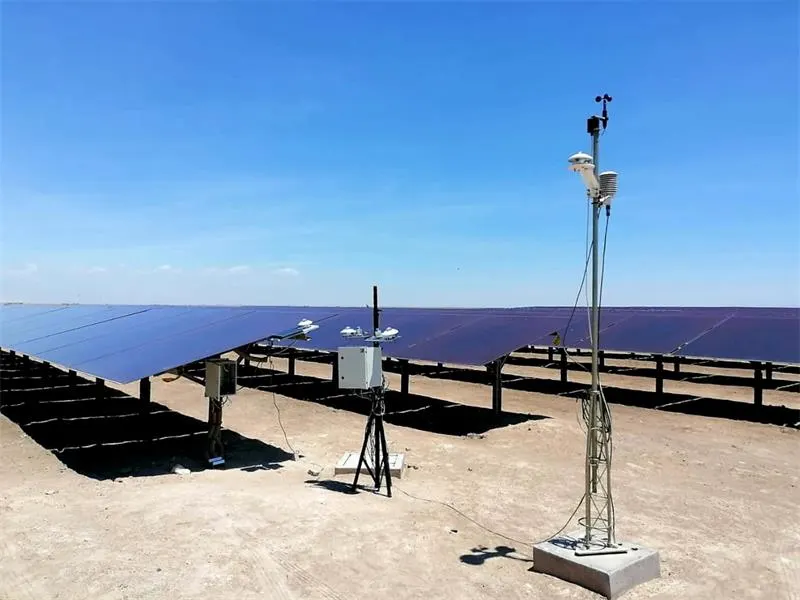
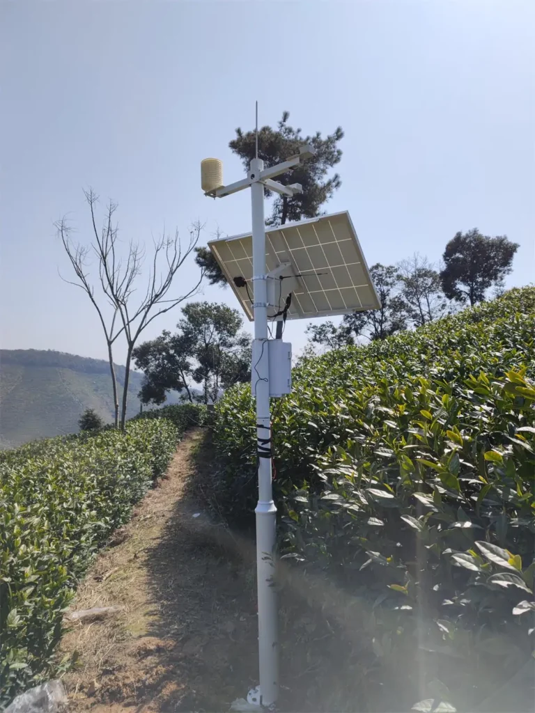
A PV monitoring system typically includes sensors, mounting hardware, a data logger, a communication link, and monitoring software. Sensors measure conditions at the site, and the mounting hardware keeps them in the required position. The data logger reads the sensor signals and records measurements, while the communication link transfers the data to a local or remote platform for viewing and analysis.
During installation, the whole measurement chain needs to be checked. Sensor output signals must match the logger’s supported inputs, and channel settings, measurement units, sampling intervals, and communication parameters must be configured correctly. A sensor that is physically installed but incorrectly configured may still produce missing or misleading data. Checking the recorded values and confirming that they reach the monitoring platform helps establish whether the system is ready for use.
For a closer look at PV monitoring system components and their functions, see our guide to the PV environmental monitoring system.
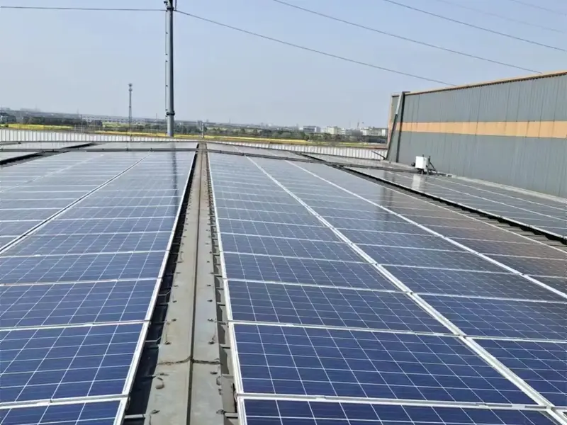
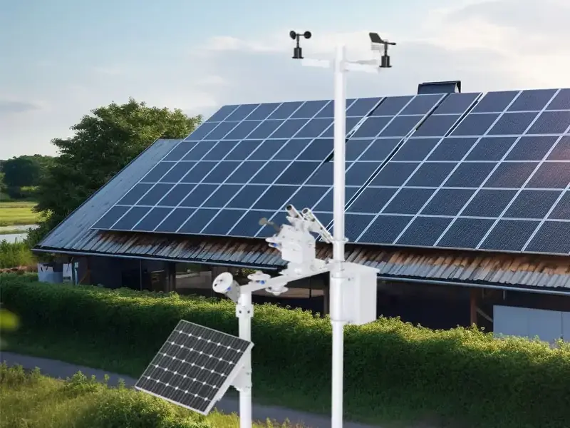
What to Check Before PV Monitoring Installation?
Before PV monitoring installation, check the site conditions, sensor specifications, data logger compatibility, and safety requirements. These checks help determine sensor locations, confirm equipment compatibility, and reduce avoidable integration problems.
Site Conditions and Sensor Locations
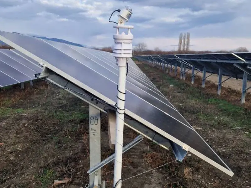
Review the PV array layout, module orientation and tilt, and whether PV monitoring system uses fixed-tilt or tracking structures. Consider shading, dust, wind exposure, extreme temperatures, and maintenance access when selecting sensor locations. The position should reflect the monitoring objective: a plane-of-array (POA) irradiance sensor should match the module plane, while installations on tracking systems must account for tracker movement and the intended measurement approach.
Sensor Specifications and Data Logger Compatibility
Before installation, verify each sensor’s measurement range, accuracy, output signal, power requirements, and communication interface against the data logger’s capabilities. Check the wiring, measurement units, and configuration requirements in the equipment manuals. A sensor can produce an output without the logger interpreting it correctly, resulting in inaccurate or missing data.
Installation Materials and Safety Requirements
Prepare the mounting hardware, cables, connectors, and weatherproofing materials required by the equipment and site conditions. Check wiring diagrams, grounding and surge protection requirements, and site safety procedures before work begins. Sensor signal wiring, PV DC circuits, and grid-side equipment must follow their respective design and safety requirements; MC4 connectors and battery-controller wiring sequences are not universal steps for environmental monitoring systems.
How to Install a PV Monitoring System Step by Step?
PV monitoring installation typically involves five stages: selecting monitoring points, mounting sensors, connecting sensors to the data logger, configuring data collection, and verifying PV monitoring system operation. The installation sequence and requirements depend on the sensor specifications, PV array configuration, data acquisition equipment, and project design.
Step 1: Select Representative Monitoring Points
Monitoring points should reflect the PV array conditions that the system is intended to measure. Before installation, review the array layout, module orientation and tilt, tracker configuration, potential shading, and access for maintenance.
- Fixed-tilt arrays: Select irradiance measurement locations that represent the relevant module plane and monitoring area.
- Tracking arrays: Confirm how tracker movement affects sensor orientation and whether the mounting arrangement matches the intended measurement approach.
- Arrays with different orientations or operating conditions: Assess whether separate measurement points are needed to capture meaningful differences between array sections.
The number and location of sensors should follow the monitoring objectives and project design. Where array sections have substantially different orientations, shading conditions, or operating environments, a single measurement point may not adequately represent the entire plant.
Step 2: Install Irradiance and Weather Sensors
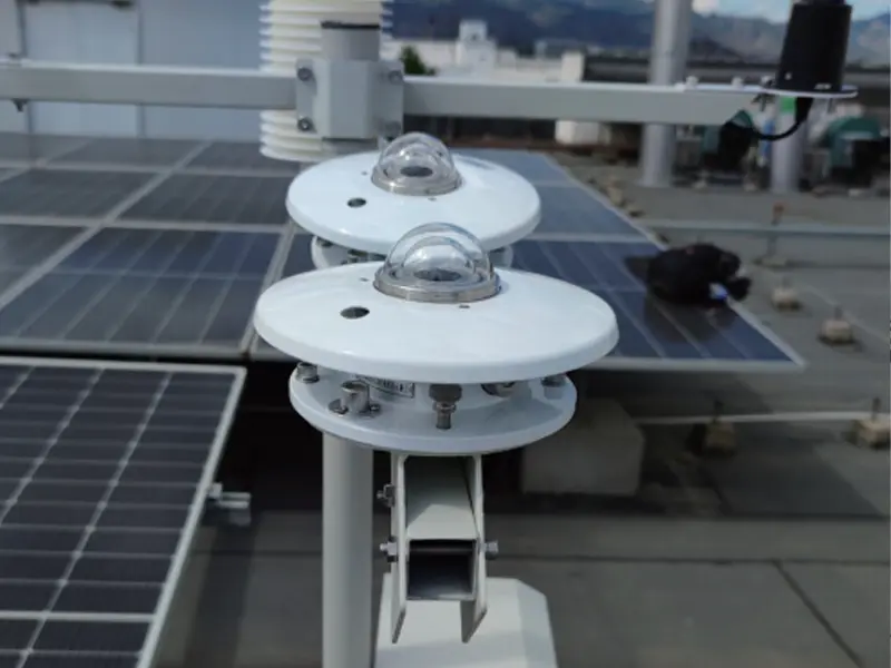
Mount each sensor according to its measurement purpose and the manufacturer’s installation instructions. Incorrect alignment, poor thermal contact, direct solar heating, or nearby obstructions can affect readings even when the sensor itself is functioning normally.
| Sensor | Key installation check |
| Solar irradiance sensor | Align the sensor with the intended measurement plane. Follow the manufacturer’s requirements for mounting, orientation, and leveling. |
| Module temperature sensor | Ensure firm thermal contact with the module backsheet and secure the sensor without damaging the module or compromising the attachment. |
| Ambient temperature sensor | Follow the specified shielding and exposure requirements to reduce direct solar heating and heat transfer from nearby surfaces. |
| Wind speed and direction sensors | Check mounting orientation, exposure, nearby obstructions, and whether the location represents the conditions being monitored. |
For projects using a dedicated weather station, see our guide to the PV weather station for an overview of its measurements and role in solar plant monitoring.
Step 3: Connect Sensors to the Data Logger
Before connecting the wiring, verify each sensor’s output type, supply requirements, polarity where applicable, terminal assignments, and compatibility with the data logger’s supported inputs. Analog and digital sensors may require different wiring and configuration, so connections must follow the documentation for the specific equipment.
After wiring, check terminal security, cable routing, strain relief, and weatherproofing. Grounding and surge protection should follow the system design, equipment instructions, and applicable site requirements. Do not assume that the same wiring arrangement applies to every sensor or data logger.
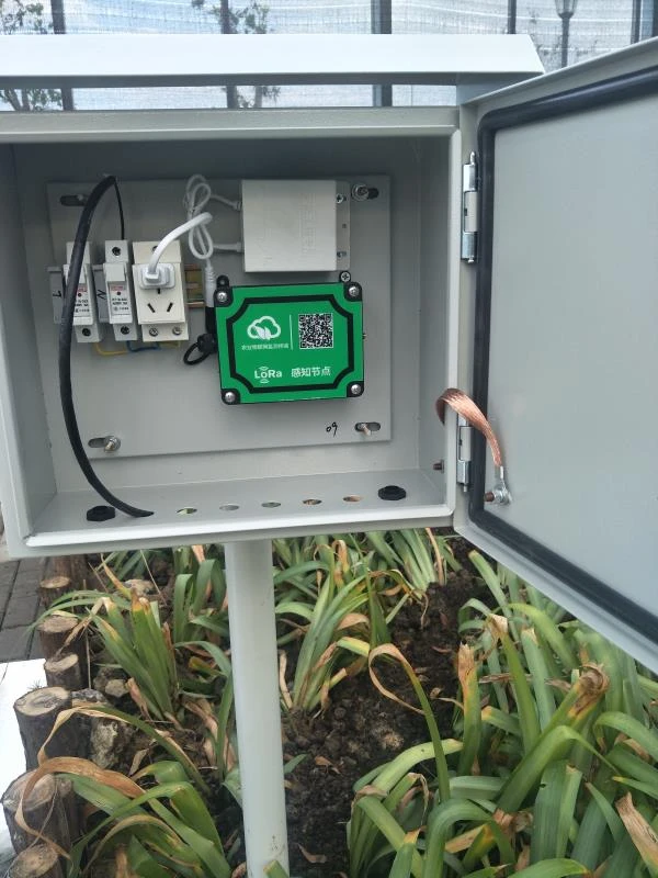
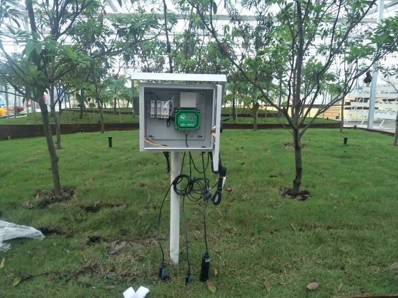
Step 4: Configure Data Collection and Communication
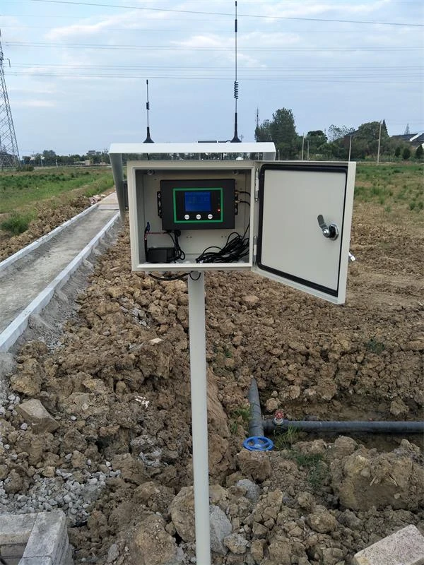
Once the sensors are connected, configure the data logger so that each input is interpreted correctly and the readings reach the intended monitoring platform.
Check the following settings:
- Channel mapping: Confirm that each logger channel corresponds to the correct sensor.
- Measurement configuration: Verify sensor type, measurement units, scaling, and any required conversion settings.
- Communication: For Modbus devices, check the device address, baud rate, parity, register mapping, and other parameters required by the equipment.
- Data recording: Confirm the sampling interval, timestamps, and field mapping on the monitoring platform.
- Remote transmission: Verify that the selected network connection and platform interface are operating as intended.
A successful network connection does not guarantee correct data. Incorrect channel assignments, register mappings, or measurement units can still produce missing or misleading records.
Step 5: Verify Readings and Record Installation Details
After installation, verify that sensor readings are received by the data logger and displayed correctly on the monitoring platform. Compare values at different points in the measurement chain where possible, and check whether the readings are consistent with current site conditions and the sensors’ measurement ranges. If data is missing or unexpected, inspect the sensor mounting, wiring, channel configuration, measurement units, and communication settings before concluding that the sensor is faulty.
Before handover, record each sensor’s model, serial number, installation location, mounting orientation, logger channel, and relevant configuration settings. Include communication test results and any unresolved issues. These records give commissioning and O&M teams a reference for troubleshooting, sensor replacement, and subsequent data-quality checks.
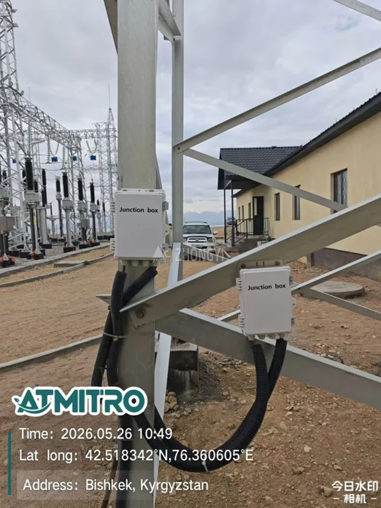
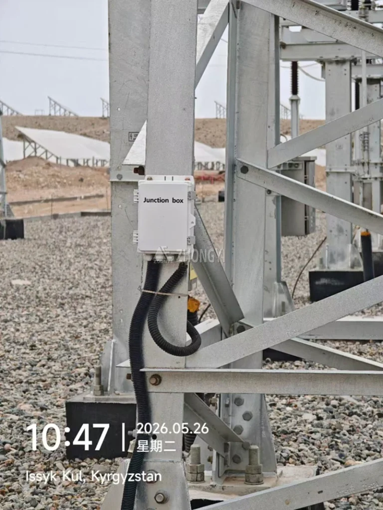
How to Position PV Monitoring Sensors for Accurate Data?
Sensor placement should match the measurement objective and PV array configuration. Even when sensors meet their specified accuracy, incorrect positioning or inconsistent installation conditions can make the collected data less representative of the array.
POA Irradiance vs. GHI
Plane-of-array (POA) irradiance measures solar radiation received on the plane of the PV modules, while global horizontal irradiance (GHI) measures solar radiation on a horizontal plane. The two measurements serve different purposes and should not be treated as interchangeable.
For POA irradiance sensor placement, align the sensor’s measurement plane with the relevant module plane when monitoring irradiance received by the array. For GHI measurements, install the sensor horizontally according to the manufacturer’s instructions. The required setup depends on the monitoring objective. For practical guidance on measurement methods and sensor setup, see How to Measure Solar Irradiance for Photovoltaic Systems. To understand the differences between GHI, direct normal irradiance (DNI), and diffuse horizontal irradiance (DHI), see What Is GHI, DNI, and DHI in Solar Energy?.
Correct Placement of Module Temperature Sensors
Module temperature readings depend on sensor location and thermal contact with the module. Poor attachment or an air gap between the sensor and the backsheet can cause readings to differ from the actual surface temperature.
For module temperature sensor installation, follow the manufacturer’s instructions and the project’s measurement plan. Secure the sensor firmly against the module backsheet without damaging the module. When comparing temperatures across modules or array sections, keep the mounting method consistent and account for differences in shading, orientation, and operating conditions.
Sensor Placement for Fixed-Tilt and Tracker Systems
Fixed-tilt arrays maintain a set orientation, while tracking systems change position during operation. On tracker systems, sensor mounting must account for movement, mechanical clearance, and the intended measurement plane. A sensor arrangement that works for a fixed-tilt array may not provide representative readings throughout a tracker’s operating range.
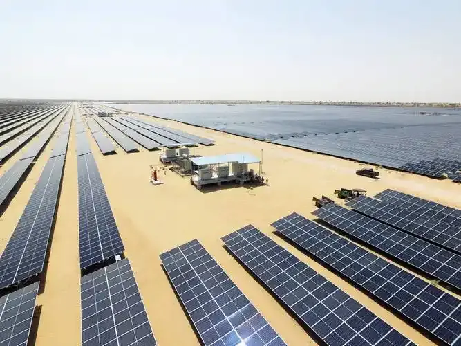
For bifacial PV monitoring installation, consider whether the project requires irradiance measurements on both the front and rear sides of the modules. Rear-side readings vary with ground reflectance, row spacing, mounting structures, cables, and shading. Sensor locations should reflect the array layout and monitoring objectives rather than assuming that a single measurement point represents the entire plant.
How to Check Monitoring System After PV monitoring installation?
After installation, verify that sensor readings are correctly recorded, data is transmitted to the monitoring platform, and historical records are complete. During PV monitoring system commissioning, focus on three checks:
- Sensor readings and communication: Confirm that sensor readings reach the data logger and monitoring platform. Check measurement units, channel assignments, and communication status. Compare readings with sensor specifications and actual site conditions; receiving numerical values alone does not confirm correct measurement.
- Data consistency and missing records: Check timestamps, sampling intervals, data uploads, and historical records for missing or irregular data. When comparing environmental measurements with inverter data, align the time periods and account for differences in units and data aggregation. Assess whether changes in irradiance and electrical output are consistent with operating conditions rather than expecting their values to match directly.
- Commissioning records: Document test results, sensor and data logger configurations, communication settings, and unresolved issues. Record configuration changes made during commissioning. Set trial-run duration and acceptance criteria according to project specifications, equipment requirements, and the contract.
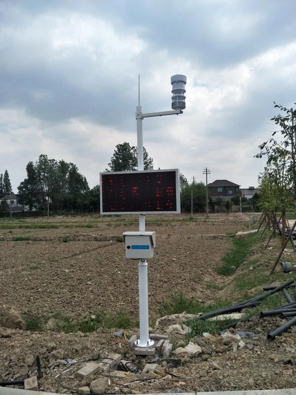
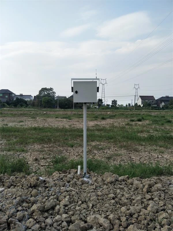
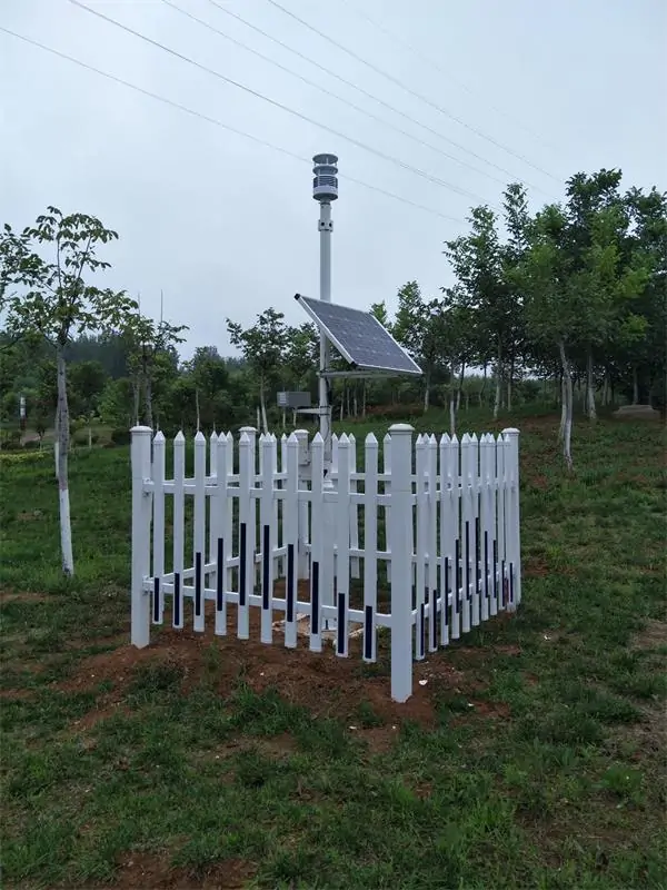
Common PV Monitoring Installation Problems
PV monitoring data can be misleading when sensor readings do not reflect site conditions or data is lost between the sensor and monitoring platform. For PV monitoring system troubleshooting, start with the observed symptom and check the most likely causes before replacing hardware.
| Problem | Possible causes | What to check first |
| Irradiance readings are lower than expected | Dirt on the sensor, shading, incorrect alignment, or different measurement planes | Check the sensor surface, nearby obstructions, mounting orientation, and whether the reference reading uses the same measurement plane and comparable conditions. |
| Sensor data is missing or unstable | Power supply or wiring issues, incorrect channel settings, communication faults, or interrupted data uploads | Check power and connections first, then verify logger channel settings and communication status. Identify whether data is missing at the sensor, logger, or platform level. |
| Module temperature readings appear incorrect | Poor contact with the module backsheet, loose mounting, different measurement locations, or mismatched timestamps | Check sensor contact and attachment, confirm the installation location, and compare readings taken under comparable operating conditions and time periods. |
How to Maintain PV Monitoring Sensors After Installation?
Regular PV monitoring system maintenance helps preserve measurement quality and prevent avoidable data issues. Maintenance intervals should follow sensor specifications, site conditions, and project requirements.
Clean Sensors and Inspect Mounting Hardware
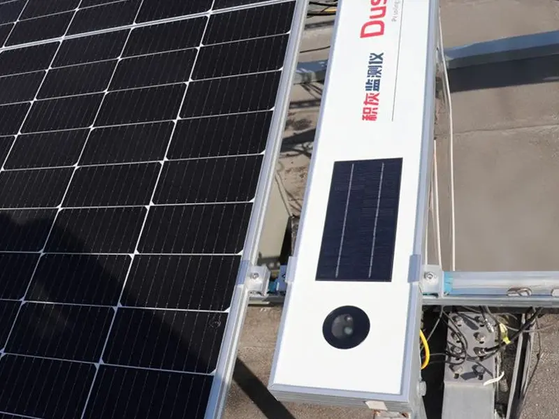
Dust, bird droppings, and other deposits can affect irradiance readings. Clean sensor surfaces according to the manufacturer’s instructions and avoid abrasive materials. Check mounting brackets, fasteners, cables, connectors, and enclosure seals for looseness, damage, corrosion, or water ingress. For module temperature sensors, confirm firm contact with the module backsheet; for wind sensors, check for obstructions or restricted movement.
Review Data Quality and Calibration Requirements
Review PV monitoring installation data quality by checking for missing records, abnormal fluctuations, communication interruptions, and persistent measurement deviations. Before attributing an anomaly to sensor drift, check site conditions, sensor placement, and data configuration.
For solar sensor calibration, follow manufacturer recommendations, applicable standards, and project requirements. Reference-instrument comparisons can help identify deviations but do not necessarily replace formal calibration. Record calibration results, sensor replacements, and configuration changes for future maintenance and troubleshooting.
Conclusion
Successful PV monitoring installation depends on more than mounting sensors and connecting cables. Sensor placement, measurement requirements, data logger compatibility, and communication settings must work together to deliver accurate, complete, and usable data. Post-installation checks help identify measurement errors and data gaps before PV monitoring system enters routine operation.
Yantai Sensor provides environmental monitoring systems, weather stations, and sensors for photovoltaic applications. Contact our team with your project requirements, measurement parameters, and integration needs to discuss suitable equipment and system configuration.